Honeywell Diagram Wiring Thermostat Ct51n

Honeywell Thermostat Cm67 Manuals

Sensi Thermostat Wiring Diagram Honeywell Thermostats

Honeywell Thermostat Wiring Instructions Thermostat Wiring

Unique Westinghouse Electric Furnace Wiring Diagram Diagram

New Honeywell Thermostat T87 Wiring Diagram Diagram

Unique Wiring Diagram For Honeywell Thermostat Rth2300b Diagram

You ll probably see a thermostat jumper wire connecting the rc and rh terminals.
Honeywell diagram wiring thermostat ct51n. Our wiring diagrams section details a selection of key wiring diagrams focused around typical sundial s and y plans. The table above provides a more complete list of honeywell thermostat wiring colors and their uses. The wiring for your honeywell thermostat depends on the functions of your heating and cooling system. Use our helpful tool to take an assessment of the existing wiring in your home.
It s there so you can supply power to the heating and cooling switches with a single wire which is usually red. Use our helpful tool to take an assessment of the existing wiring in your home. Find out if your home is compatible with a honeywell home thermostat. The honeywell home trademark is used under license from honeywell international inc.
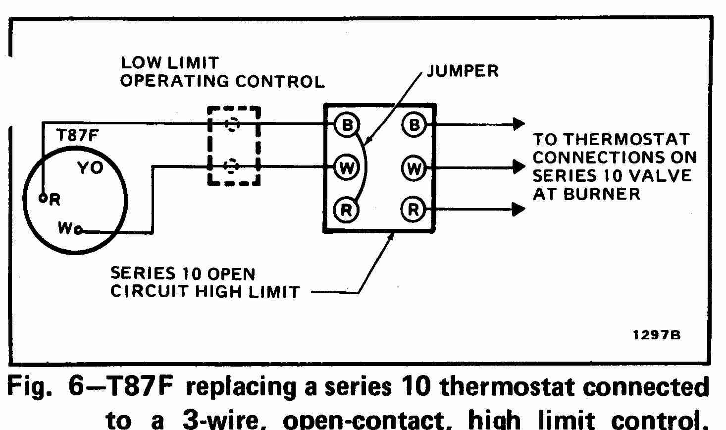
The t87f is adaptable to most 2 wire 24 to 30 volt heating systems and to most 3 wire 24 to 30 volt heating systems controlled by a series 10 thermostat. Disconnect power supply before connecting wiring to prevent electrical shock or equipment damage. At left the thermostat wiring diagram illustrates use of a honeywell t87f thermostat in a 3 wire application as a spdt single pole double throw switch such as used to control low voltage motors electric radiator valves zone valves. All wiring must comply with local electrical codes and ordinances.
3 wire spdt honeywell t87f thermostat wiring diagram. Honeywell thermostat wiring diagram 4 wire examples.

Unique Honeywell T6360b Room Thermostat Wiring Diagram Diagram

New Honeywell Central Heating Thermostat Wiring Diagram Con

Thermostat Wire Diagram In 2020 Thermostat Wiring Honeywell

Lovely Wiring Diagram For Honeywell S Plan Diagrams

Honeywell 5000 Wiring Diagram With Images Honeywell

Intertherm Thermostat Wiring Diagram Med Billeder
799 6 Heat Stove Switch Wiring Diagram Wiring Resources

New Honeywell Central Heating Thermostat Wiring Diagram Combi

New Honeywell Thermostat Rth7600 Wiring Diagram Diagram

Wiring Diagram Honeywell Thermostat Wiring Diagram For Wire New

Unique Wiring Diagram For Honeywell T6360 Thermostat Diagram

Honeywell Thermostat Ct87n Wiring Diagram Wiring Diagram

Wiring Diagram For Central Heating System S Plan Central Heating
