Ct Differential Wiring Diagram
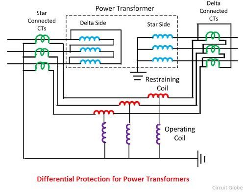
Transformer Differential Protection Scheme
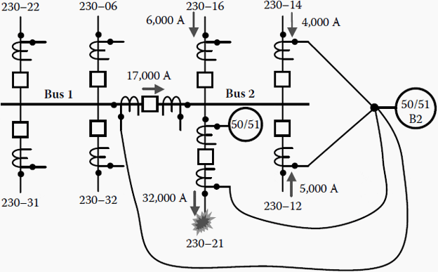
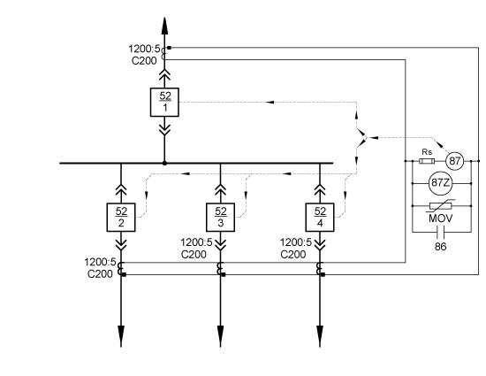
Bus Protection Overcurrent Differential

Ct Polarity In Differential Protection Electric Power
Differential 87 Current Protection Electric Power Measurement

Exploring The World Of Medium Voltage Switchgear Differential

Wiring Current Transformers For Differential Protection Pac Basics

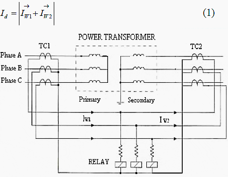
If this difference is equal to or greater then the pickup level a trip will occur.
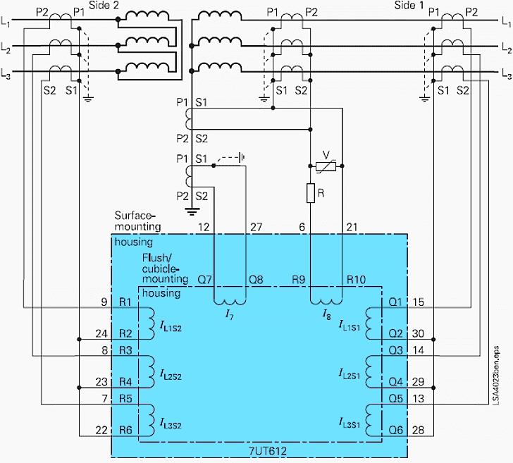
Ct differential wiring diagram. A window ct has a ratio of 100 5 placing two primary con ductor wraps two primary turns through the window will change the ratio to 50 5. Problems and solutions david costello jason young and jonas traphoner schweitzer engineering laboratories inc. Allentown pa abstract more and more sub stations are retrofitted with numerical relays meters and monitoring devices. Differential scheme it is necessary to understand its basic operation.
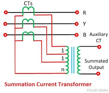
Wiring current transformers for differential protection. Selection of current transformers wire sizing in substations sethuraman ganesan abb inc. Current transformer wiring diagram instructions note. Some types of equipment employ this method to calibrate the equipment or to permit a single ratio ct to be utilized for several different ampacities of equipment.
The diagram below can be used to select wire size if the lengths of the leads are known. Most often the older relay gets replaced with a newer relay with the rest of the installation such as current transformer ct and lead. Be sure to connect the white wire to the phase terminal aligned with the white dot and the black wire to the terminal with the black dot. Wiring current transformers for differential protection.
In modern microprocessor based relays phase compensation. The terminals are labeled øa ct øb ct and øc ct. Abstract paralleling current transformers cts is a common practice in differential or line protection applications. 1 paralleling cts for line current differential applications.
We supply these meters on the assumption that they will be installed by a qualified electrician familiar with the installation of metering equipment ensure all current transformers are installed as per wiringdiagram which can also be. The differential element subtracts the current coming out of each phase from the current going into each phase and compares the result or difference with the differential pickup level. Bar type ct s have primary connections that. The polarity of each pair of terminals is indicated by a white and black dot on the label.
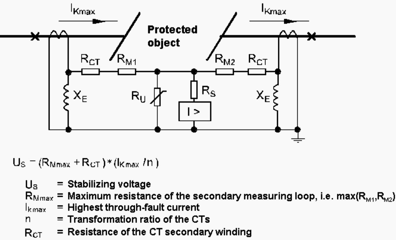
The highimpedance differential scheme introduces a high value stabilizing resistor e g 2 000 ohms in the differential branch of the circuit to reduce the differential current resulting from heavy ct saturation during external faults. Window bushing bar and wound the primary winding can consist merely of the primary current conductor passing once through an aperture in the current transformer core window or bar type or it may consist of two or more turns wound on the core together with the secondary winding wound type. There are four typical types of current transformers.
Transformer Differential Protection Ansi Code 87t
High Impedance Busbar Differential Protection Valence Electrical

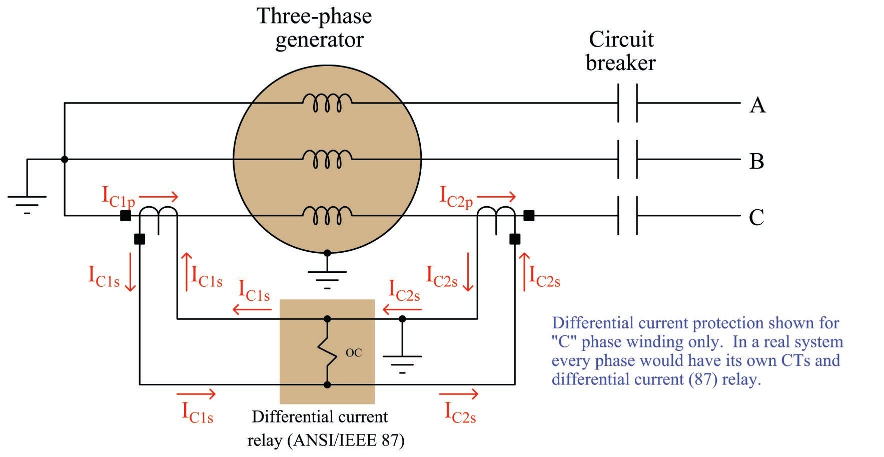
Generator Differential Protection System Assignment Point
Differential Protection Of A Transformer Working Problem

Current Transformer Circuit Diagram Download Scientific Diagram
Differential Protection Of Transformers Machines Busbars Lines
Https Www Eiseverywhere Com File Uploads 319c7dce0d5a35f15574dafad9f696c7 Current Transformers For Hors 2017 Pdf

High Impedance Protection Ct Connection For 5 Ct Arrangement
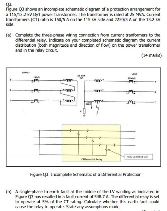
Solved Q3 Figure Q3 Shows An Incomplete Schematic Diagram
Https Www Gegridsolutions Com Products Brochures Alstomenergy Ga Protection Control Relays Grid Ga L3 Mcag 14 34 0728 2015 12 En Pdf

Motor Protection For This Millennium Ppt Video Online Download
What Is A Differential Relay Quora
I Want To Know How A High Impedance Differential Scheme Works